Cooling architecture determines how much hashrate a fleet can actually sustain, not just how a single ASIC miner performs on a datasheet. Air, hydro and immersion systems each shift where heat is removed, how much auxiliary power that removal consumes, and how quickly a technician can service a failed component without pulling down an entire row. For institutional buyers, that makes cooling a capital and operating decision with its own lifecycle math, distinct from the hashrate and J/TH figures printed on a manufacturer spec sheet.
Cooling is now treated as part of the profit model for large sites rather than a secondary hardware detail, since it affects chip temperature, power stability, repair frequency, noise and deployment density together, as described in an analysis of cooling design in Bitcoin mining economics. For most institutional buyers, the right architecture is the one that matches a site’s power density, water access and service model, with air cooling suited to lower-density retrofits, hydro cooling suited to high-density sites with engineering discipline, and immersion suited to facilities needing acoustic control and thermal stability at scale. Operators researching specific machine specifications and fleet comparisons can find model-level data in the miner-bitcoin.com ASIC miner specifications reference before evaluating which cooling path fits a given deployment.
Key Takeaways
- Cooling architecture affects hashrate stability, hardware lifespan and total facility power draw, not just individual machine temperature.
- Air, hydro and immersion systems carry different auxiliary power loads, retrofit costs and serviceability profiles that should be measured separately from ASIC-level J/TH.
- Procurement decisions should treat cooling as an auditable engineering choice, with acceptance testing, warranty terms and lifecycle costs documented before deployment.
Why Cooling Architecture Is a Core Infrastructure Decision
Thermal design shapes whether a fleet can sustain rated hashrate over time, how quickly components degrade, and how much of a site’s power budget goes to cooling rather than compute. Cost-benefit analysis at the fleet level needs to weigh mining scale, environmental exposure and mining profitability against the capital and operating cost of each cooling path, because a decision made at the rack level compounds across hundreds or thousands of units.
How Thermal Conditions Affect Hashrate, Availability and Component Wear
Sustained heat exposure changes ASIC behavior in ways that show up as throttling, intermittent faults or reduced availability rather than immediate failure. Firmware protection logic on many machines actively limits performance once chip temperatures cross defined thresholds, which converts a thermal problem into a hashrate and uptime problem before it becomes a hardware failure. Component wear accelerates under repeated thermal cycling, affecting hashboards, fans and power delivery components differently depending on how consistently the cooling system holds target temperature.
Defining the Boundary Between Machine Efficiency and Facility Efficiency
ASIC-level efficiency, expressed in joules per terahash, describes only the chip and board power draw under stated conditions. Facility efficiency adds every watt spent on fans, pumps, chillers and heat rejection equipment needed to keep that chip at its rated operating point. Comparing two architectures fairly requires separating these two measurement boundaries rather than citing a chip-level J/TH figure as if it were the whole site’s energy cost.
When Cooling Constraints Determine Fleet Density and Site Design
Cooling capacity, not power availability alone, often sets the practical ceiling on how many machines a site can run per square foot. Rack density, service lane width, acoustic limits and airflow paths are all downstream of the chosen cooling architecture, which means the cooling decision needs to happen early in site design rather than after electrical infrastructure is finalized.
Thermal Load and Heat-Rejection Fundamentals
Every watt an ASIC miner draws from the wall becomes heat that the facility must remove, and the path that heat takes from chip to outdoor environment defines the engineering requirements for fans, pumps, heat exchangers and chillers. Getting this conversion right, rather than working from a manufacturer’s headline power figure, is the starting point for any credible cooling design.
Converting ASIC Power Consumption Into a Facility Heat Load
Facility heat load calculations should use complete wall power measured under design conditions, not catalogue power, because wall power includes power supply losses and auxiliary draw that a chip-level spec omits. A rigorous heat rejection calculation records room and duct temperatures, air density assumptions, fan curves and seasonal ambient data as evidence, then applies a calculation sheet checked against measured commissioning temperatures, according to a breakdown of ASIC heat rejection calculation methodology. Treating hardware purchase price, electricity rate and pool performance as separate line items from the heat-load figure keeps the calculation auditable months later.
Heat Transfer Paths From Chips to the Outdoor Environment
Heat moves from the chip through a heatsink or water block, into air or coolant, and eventually to an outdoor heat exchanger, cooling tower or ambient exhaust point. Each transfer step introduces a temperature difference and a potential bottleneck; a duct that restricts airflow or a coolant loop with an air pocket can make theoretical heat rejection capacity unavailable at the miner even when the outdoor-side equipment is sized correctly. Recirculation of exhaust air back into intake air is one of the more common failure points in this chain, since it raises effective inlet temperature without appearing on a simple wall-power audit.
How to Measure Thermal Performance Without Misstating J/TH
J/TH figures published by manufacturers describe the ASIC and its stock cooling configuration under stated test conditions, not the facility’s total energy draw. A defensible thermal performance measurement uses matched time periods for wall energy, pool-accepted hashrate and temperature logs, and states whether each figure is measured, manufacturer-supplied or assumed. Mixing a chip-level efficiency figure with a site-level cooling overhead number without labeling the boundary produces a misleading efficiency claim.
Air-Cooled Fleet Design
Air cooling remains the default architecture for a large share of institutional deployments because it uses familiar fans, ducts and filtration rather than a coolant loop or dielectric fluid system. Its performance depends almost entirely on how well the facility manages airflow direction, filtration and dust, since the ASIC’s built-in fans can only move air the room lets them move efficiently.
Airflow Management, Pressure Balance and Ductwork
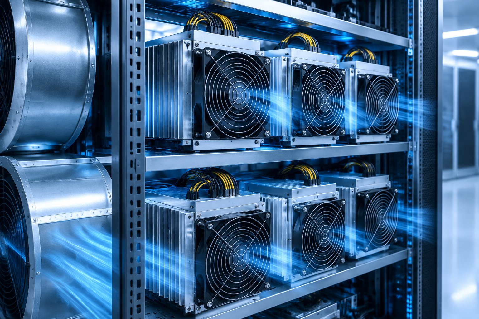
Effective air cooling depends on separating cold intake air from hot exhaust air along a defined path, typically using negative-pressure containment with a hot aisle exhausting outdoors. In many small and mid-sized deployments under 2 MW, the negative pressure created by ASIC exhaust fans is enough to draw in cool air without dedicated intake fans, an airflow approach common in container-based mining sites, according to a technical overview of Bitcoin mining facility airflow design. Ductwork sizing and pressure balance across rows matter because uneven pressure creates hot spots even when total site airflow capacity looks adequate on paper.
Filtration, Dust Accumulation and Heatsink Condition
Dust accumulation on heatsinks and fan blades reduces heat transfer efficiency over time, which forces fans to work harder to hold the same chip temperature and raises both noise and power draw. A clean machine running at a lower fan speed can hash more and run quieter than a dusty one pushed to a higher fan speed, since firmware target-temperature logic will drive fans toward the ceiling as heatsinks lose thermal contact efficiency, per documented ASIC cooling mode and fan-speed guidance. Filtration policy should match the site’s ambient dust load, with inspection intervals set by observed accumulation rather than a fixed calendar schedule alone.
Preventing Hot-Air Recirculation and Localized Heat Spots
Recirculation happens when exhaust air finds a path back to intake air, raising effective inlet temperature above the design assumption and reducing the cooling margin every machine in that zone was sized against. Localized heat spots often trace back to a blocked duct, a gap in row-end containment or a fan operating outside its rated curve. Facility teams evaluating machines for a given deployment can reference the Antminer S19 family’s published thermal and power figures when planning airflow margins for a specific rack layout.
Hydro-Cooled Fleet Design
Hydro cooling replaces the ASIC’s air-side heat path with a closed coolant loop, moving heat from a water block on the hashboard to an external heat exchanger rather than relying on room air. This raises achievable rack density but also raises the facility’s engineering and commissioning burden compared with air cooling.
Coolant Loops, Manifolds and Water Blocks
A hydro-cooled fleet is a complete thermal system consisting of the miner, manifolds, pumps, heat exchanger, filters, sensors and controls, not a feature of the miner alone, and the miner’s advertised power figure does not describe the total site consumption of that system, according to a guide to hydro-cooled miner commissioning requirements. Manufacturer manuals specify required coolant chemistry, flow rate, pressure and temperature range for each hardware revision, and those values are not interchangeable across generations of the same product line. Ordinary tap water is not universally suitable as a coolant, and vendor-specified water or coolant treatment should be followed rather than substituted.
Pumps, Flow Control and Pressure-Drop Management
Pump sizing and pressure-drop management across manifolds determine whether every rack receives adequate flow at design ambient conditions, and a loop that performs adequately in cool weather can become inadequate during peak heat if capacity margin was not built in. Some hydro ASIC firmware includes startup protections that block operation if the spread between the highest and lowest chip temperature exceeds a defined threshold, or if temperatures fall outside a stated range, which is a protective measure against uneven flow rather than a fault condition, according to documented firmware limits for hydro ASIC versions. Monitoring should track inlet and outlet temperatures, flow and pressure behavior together, since shared symptoms across a loop point to a system-level issue rather than a single failed unit.
Chillers, Cooling Towers and Secondary Heat-Rejection Loops
The outdoor side of a hydro system, whether a dry cooler, chiller or cooling tower, has to be sized against the facility’s full heat load and worst-case ambient temperature, not an average condition. As a reference point for scale, one manufacturer’s 40-foot hydro-cooling container is rated for 1.2 or 2.4 MW of cooling capacity supporting up to 240 hydro ASIC units, with a water flow rate near 26,400 gallons per hour and water inlet temperature specified at 104°F at a 95°F ambient, according to BixBit USA’s hydro-cooling container specifications. Facility teams should confirm that secondary loop capacity, redundancy and maintenance access allow isolating a single unit without disrupting the rest of the row.
Immersion System Design and Fluid Governance
Immersion cooling submerges ASIC hardware directly in a dielectric fluid, eliminating the air-side heat path entirely rather than moving it to a coolant loop. The engineering discipline shifts toward fluid selection, compatibility verification and external heat rejection design, since the tank itself is only one component of a working system.
Single-Phase and Two-Phase System Boundaries
Single-phase immersion keeps the dielectric fluid in liquid form throughout the loop, while two-phase systems rely on the fluid boiling at the heat source and condensing elsewhere, a design that removes more heat per unit of fluid but adds fluid cost and system complexity that is typically unnecessary for standard Bitcoin mining ASIC deployments. Most institutional mining immersion deployments use single-phase systems for this reason, reserving two-phase designs for niche high-density applications.
Dielectric Fluid Selection, Testing and Handling
Fluid selection should be based on verified compatibility between the exact device, its power supplies and the specific dielectric fluid, since different fluids carry different handling, compatibility and maintenance requirements, and substituting water or an unverified liquid is not appropriate, per a guide to evaluating immersion cooling compatibility and total cost. Firmware cooling settings must match the physical installation, because an immersion setting applied to an air-cooled miner can disable checks that its fans and air-side thermal design still depend on. Fluid handling and eventual replacement or disposal requirements from the supplier should be included in the total cost estimate rather than treated as a later problem.
Tank Layout, Circulation and External Heat Rejection
Tank design needs to account for circulation pumps, heat exchangers, filtration, sensors, controls and safe access for lifting, draining and servicing units, alongside electrical demand from auxiliaries in addition to the miners themselves. Direct contact between chips and dielectric fluid supports rapid, uniform heat dissipation that can help prevent thermal throttling under sustained load, according to a technical explainer on immersion cooling function for ASIC miners. A representative pilot, measuring accepted hashrate, total wall power and stable temperatures against a documented air-cooled baseline, gives a defensible basis for scaling the design rather than extrapolating from a brief peak-performance demonstration.
Energy Efficiency, Firmware and Performance Modes
Total facility energy draw for a cooled fleet always exceeds the sum of ASIC-rated power figures, because pumps, fans, chillers and controls add auxiliary load on top of chip-level consumption. Firmware governance interacts directly with this picture, since fan curves and thermal targets determine how much of that auxiliary load a given cooling architecture actually needs.
Separating ASIC J/TH From Cooling-System Auxiliary Power
A defensible efficiency comparison states ASIC J/TH and cooling-system auxiliary power as two separate figures with their own measurement boundaries, rather than blending them into a single number. Auxiliary power for air cooling is largely built-in fan draw, while hydro and immersion systems add pump, chiller and heat-exchanger load that must be metered separately to produce a comparable total-cost figure.
Firmware Governance Under Changing Thermal Conditions
Firmware typically runs in an automatic mode that holds fan speed to keep chips near a target temperature, commonly near 65°C, with manual PWM modes reserved for test benches and immersion-specific modes that disable fan emulation entirely, according to documented ASIC firmware cooling mode behavior. Lowering the target temperature below the default typically pushes fans toward maximum speed for a marginal gain in service life, an outcome that sits inside normal measurement variance rather than a proven durability improvement. Fleet operators should document which firmware version and cooling mode is active on each unit, since mismatched settings between physical cooling architecture and firmware configuration can remove intended protections.
Validating Performance Claims Through Controlled Site Testing
Hashrate and power claims tied to a cooling upgrade should be validated through a controlled test that holds firmware, ambient conditions and measurement instruments constant across a baseline and a changed configuration. A short test window can confirm that a system starts and reports a hashrate; it does not establish stable performance under sustained load, heat soak or seasonal ambient swings. Recording raw wall-power and pool-accepted-share logs for the test period, rather than relying on dashboard summaries, keeps the evidence auditable for later review.
Maintenance, Reliability and Serviceability
Maintenance requirements differ substantially by cooling architecture, and each one carries its own failure modes, inspection intervals and skill requirements. Planning maintenance staffing and spare-parts inventory around the specific architecture in use, rather than a generic ASIC maintenance checklist, reduces avoidable downtime.
Routine Inspection and Condition Monitoring by Architecture
Air-cooled fleets need routine inspection of filters, fan condition and heatsink cleanliness, since dust accumulation is gradual and detectable before it causes a fault. Hydro and immersion fleets need monitoring of flow, pressure, fluid condition and leak-detection alarms, with inlet and outlet temperature comparisons used to catch drift from baseline before a fault propagates across a shared loop.
Common Failure Modes in Fans, Filters, Pumps and Heat Exchangers
Fan failures on air-cooled units often present first as a Hall-sensor fault that misreports speed while the impeller still spins, a condition firmware can be configured to tolerate temporarily by lowering the minimum required fan count as a stopgap rather than a permanent setting, per documented ASIC firmware fan-count protection logic. Pump and heat-exchanger faults in hydro or immersion systems typically show up as abnormal noise, vibration or a leak at an accessible connection point, and inspection should never involve opening energized equipment to investigate. Filters in both air and hydro systems degrade gradually, and a clean, well-maintained machine running at moderate fan speed can hash more consistently than a neglected one forced to run fans at a higher speed.
Thermal Interfaces, Repairs and Controlled Return-to-Service
Thermal paste replacement and hashboard-level repairs require controlled procedures, since applying the wrong volume or type of interface material can create localized hot spots that firmware may misread as a board-wide issue. Returning a repaired unit to service should follow a documented commissioning sequence, including leak checks for hydro and immersion systems and a burn-in period with logged temperature and hashrate data before it rejoins full production.
Facility Integration, Retrofit and Operational Risk
Cooling architecture choices ripple into electrical design, mechanical systems and site controls, and retrofitting an existing site to a different architecture carries constraints that a new-build site does not face. Facility teams should treat these integration requirements as part of the cooling decision rather than a downstream implementation detail.
Electrical, Mechanical and Controls Integration Requirements
Hydro and immersion systems add electrical load for pumps, chillers and controls that must be included in facility power planning alongside ASIC load, and PLC-based monitoring and control systems for leak detection, temperature and alarms are standard on industrial-scale hydro containers. Mechanical integration includes plumbing runs, structural support for tank weight in immersion deployments, and coordination between mining, facility and maintenance teams for commissioning.
Retrofit Constraints for Air, Hydro and Immersion Deployments
Air cooling retrofits are generally the least disruptive, since they build on existing ventilation paths and fan-based maintenance routines already familiar to most site teams. Hydro cooling retrofits require adding coolant loops, manifolds and a water-quality regime, without the leak-response protocols an air-only site never needed to build. Immersion retrofits require the most significant reconstruction, since converting an air-cooled device into a liquid environment is a system change rather than simply placing existing hardware into a tank, and firmware, warranty terms and preparation procedures all need vendor confirmation before conversion.
Leakage, Fluid, Water-Quality and Environmental Risk Controls
Leak detection, water-quality monitoring and documented shutdown procedures for circulation loss or fluid contamination should exist before a hydro or immersion system goes into production, not be improvised after a first fault. Draining or refilling a coolant or dielectric fluid system incorrectly can introduce new problems, so vendor-specified procedures should govern seasonal shutdown and fluid handling. Independent protection for circulation failures, paired with a documented response to leaks or overheating, is a baseline requirement rather than an optional safeguard for any liquid-based cooling infrastructure.
Procurement and Comparative Due Diligence
Procurement decisions for cooled ASIC fleets should bind every performance and cost claim to the exact hardware revision, cooling configuration and test conditions involved, rather than relying on a general market reputation or vendor marketing. This turns cooling architecture selection into an auditable evidence trail similar to the acceptance process used for the ASIC hardware itself.
What to Request From Manufacturers and Cooling-System Suppliers
Buyers should request the exact model and hardware revision manual specifying coolant or airflow requirements, flow, pressure and temperature range, along with the electrical supply needed for auxiliary equipment. A defensible procurement requirement also defines acceptance measures ahead of price negotiation, including test duration, ambient conditions, accepted hashrate rather than a dashboard figure, and wall power measured with calibrated instruments, according to a procurement risk framework for ASIC hardware and supply-chain evidence. Operators benchmarking cooling-adjacent hardware decisions can cross-reference the ASIC miner specifications database for published power, hashrate and thermal figures by model.
Acceptance Testing for Hashrate, Power and Thermal Performance
Acceptance testing should run the complete installation at design load, measure inlet and outlet conditions, and compare results against the calculation sheet used during design. Observed behavior, including fan or pump response, temperature stability and wall power under sustained load, should be logged and matched to the same time window as pool-accepted hashrate before a unit or system is approved for full deployment.
Warranty, Spare Parts, Resale and Lifecycle Considerations
Warranty terms differ by cooling architecture, since hydro and immersion warranties commonly require documented adherence to vendor-specified fluid, pressure and installation procedures, and departing from them can affect coverage. Spare-parts planning should account for pumps, heat exchangers and fluid replacement alongside standard hashboard and fan inventory. Resale value and end-of-life disposition also depend on service history, since a unit with undocumented immersion or overclocking history carries different risk for a buyer than one with a clean, logged maintenance record.
Selecting an Architecture for Site Conditions and Fleet Objectives
Architecture selection should start from the site’s binding constraint, whether that is available floor space, water access, acoustic limits or capital budget, rather than a general preference for one traditional cooling method over another. Air cooling suits sites with workable ventilation, moderate density targets and fan-based maintenance teams already in place, since it avoids coolant loops, manifold pressure balancing and water-quality regimes entirely. Hydro cooling suits sites where rack density, airflow capacity or acoustic limits are already expensive constraints, provided the operating team can maintain pressure monitoring, filtration discipline and leak-response readiness. Immersion cooling suits sites prioritizing acoustic control and thermal stability at higher density, at the cost of the most significant retrofit and fluid-governance requirements of the three architectures.
| Factor | Air Cooling | Hydro Cooling | Immersion Cooling |
|---|---|---|---|
| Relative density | Lower | Higher | Highest |
| Noise profile | Higher | Moderate | Low |
| Retrofit complexity | Lowest | Moderate | Highest |
| Auxiliary equipment | Fans, filters | Pumps, manifolds, heat exchangers, chiller | Tanks, pumps, heat exchangers |
| Water/fluid management | None | Coolant chemistry, flow, pressure | Dielectric fluid compatibility, filtration |
No single architecture wins across every operational efficiency metric, since the mining farm’s power infrastructure, climate and maintenance capability shape which cooling solution produces the most stable outcome. Documenting the decision against measured heat load, ambient design conditions and maintenance capacity, rather than a general architecture preference, gives operators a defensible basis for the choice.
Frequently Asked Questions
What is the best ASIC miner cooling architecture for a large mining facility?
The best architecture depends on the site’s power density, water access and maintenance capability rather than a universal ranking. Hydro and immersion cooling tend to fit high-density industrial sites better than air cooling, provided the operator can maintain the added engineering discipline those systems require.
How should operators compare air-cooled and hydro-cooled ASIC J/TH?
Operators should compare J/TH figures only when both machines are tested under stated, matched conditions, and should add each system’s auxiliary power (fan draw for air, pump and chiller draw for hydro) before drawing a total-cost conclusion. A chip-level J/TH figure alone does not describe total facility energy consumption.
Does immersion cooling reduce total facility power consumption?
Immersion cooling can reduce fan-related power draw and support more stable chip temperatures, but it adds pump, heat-exchanger and fluid-handling power that must be measured separately. Whether total facility consumption falls depends on the specific system design and site conditions, not the cooling method alone.
What cooling infrastructure is required for hydro-cooled ASIC miners?
Hydro-cooled ASIC miners require a complete system beyond the miner itself, including manifolds, pumps, a heat exchanger, filters, sensors and controls, plus an outdoor heat-rejection loop such as a dry cooler or cooling tower. Coolant chemistry, flow rate and pressure must match the exact hardware revision’s manual.
Can existing air-cooled mining sites be retrofitted for immersion cooling?
Existing air-cooled sites can be retrofitted for immersion cooling, but the conversion is a system change rather than simply placing existing hardware into a tank. It requires verified fluid and equipment compatibility, firmware adjustments, structural support for tank weight, and vendor confirmation that warranty terms remain valid.
How does cooling architecture affect ASIC warranty and resale value?
Cooling architecture can affect warranty coverage, since hydro and immersion warranties commonly require documented adherence to vendor-specified installation and fluid procedures. Resale value also depends on documented service history, since units with unclear immersion or overclocking history carry more risk for a prospective buyer than units with a clean maintenance record.